Return to Previous Page
The Artillery Plunger -
Revisited
A homemade device for measuring
cannon shell fragments.
By Dave Poché
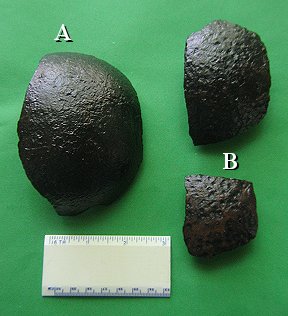 |
Ever find small cannon shell
fragments and wonder what was the size of the full shell? 6-pounder, 12-pounder
or 24-pounder? Cannon shell fragments like “A” in the picture to the left are
easy to figure but what about fragments like “B”?
Here is a
simple measuring device that can be assembled from materials available from any
hardware store and will provide the original shell sizes from “B” sized
fragments.
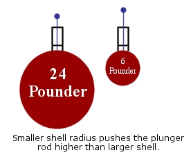
How it
works….The Plunger measures the radius of curvature of the shell fragment by
changing the height of its plunger’s rod. These height differences can be used
to estimate the actual diameter of the whole cannon shell. Larger diameter
cannon shells (24 pounder) will move the plunger rod up very little while
smaller shells (12 and 6 pounder) will move it up more. The rod height can be
measured with a caliper or something as simple as a marked wooden pencil to
estimate the size of the whole cannon shell from a small fragment of the
original.
|
 |
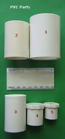
![Text Box: Here is a list of materials needed for construction:
1 – 1.25 inch PVC Slip coupling (Schedule 40) [1]*
1 – 1.0 inch PVC Slip coupling (Schedule 40) [2]
1 – 3/4 inch PVC Slip coupling (Schedule 40) [3]
1 – 3/4 inch PVC Slip plug (Schedule 40) [4]
1 – 1/2 inch PVC Slip coupling (Schedule 40) [5]
1 – 1/8 inch brass or steel stock rod
1 – small can of PVC cement
1 – small can of PVC primer
1 – tube of Duco-type Plastic Glue
Optional:
1 – small wire nut and brass washer
*Part numbers - refer to picture below](TheArtilleryPlunger%20-%20Revisited_files/image001.gif)
|
|
CONSTRUCTION:
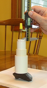
You can refer to the picture to the right to see the main PVC parts tobe used
in the construction. The numbers of the parts will be referred to in the
construction
Find the end of Part 2
which easily slides into Part 1; dry assemble these 2 parts together and set
aside.
Part 3 has 2 slip
plugs with one at each end. Place Part 4 into Part 3 and glue these together
with PVC cement. With a pen and ruler mark or scribe with lines the top of Part
4 connecting opposite corners of the plug. The common point of all the lines
should lie at the center of the top of the plug. At that center point, drill a
hole in the top of the plug beginning with a 1/16 inch drill bit and follow it
with a 1/8 inch bit. The object here is to not “egg-out” the hole
since this is where the measuring rod
will travel.
Mark the cap end as before to find the
center of Part 5 and drill a 1/8 inch hole at the center of Plug 5. Next dry
fit Part 5 into the other end of Part 3. It should not fit.
Cut off the lower end of the plug so that it fits about ¼ inch INSIDE of Part 3.
Glue Part 5 into the lower end of Part 3 with Duco-type plastic glue. Pass the
brass or steel rod stock through the two holes in the plugs and center the rod
stock. Let the Part 3 dry for about 24 hours with the rod in place.
After assembled Part 3
is dry, Return to the dry assembled Parts 1 and 2, sand or grind the exposed
inside end of the Part 2, till assembled Part 3 fits to the stop inside Part 2.
|
 |
Glue assembled Part 3 into
Part 2 with PVC cement. Be sure to check to make sure rod lies at the
center of the coupling assembly while glue is drying. Glue Parts 1 and assembled
Part 2 together with PVC or Duco-type cement. Be sure to check to make
sure rod lies at the center of the assembly as the glue drys.
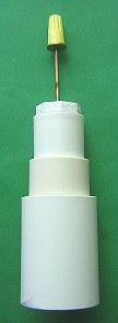
Cut the 1/8 inch brass or
steel to a length of 7 inches and attach and glue optional washer and wire nut
to one end of the rod. Assembly of the Plunger is now complete.
MEASUREMENTS
- Artillery tactical manuals of the Civil War (Gibbon, 1863 and Roberts, 1863)
suggested that there was an optimal selection of ordinance to be used on
advancing infantry and cavalry. At distances greater than 650 yards the hollow
shrapnel shell (known as the “common shell’) or filled case shot projectiles
were to be used on the enemy. Between 650 to 350 yards, solid shot should be
shot directly at advancing columns or ricocheted into the columns. At 350 yards
or less, canister should be used.
|
Optimal Selection of Artillery Ordnance |
|
Distance |
Ordnance to be used |
|
Greater than 650 Yards |
Common Shell or Case Shot |
|
650
to 350 Yards |
Solid
Shot |
|
At
350 0r less |
Canister |
Shrapnel shells and case shot were spherical and by use of a timing fuse
were intended to stop or slow the advance of the enemy by “raining down”
shell fragments on them. The table below shows the typical dimensions of
these projectiles.
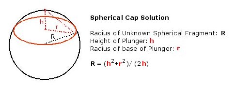
The plunger measures a circular portion of a
sphere (spherical cap) where the measured height of the plunger is equal to
h in the diagram below and the radius of the PVC cylinder touching
the surface of the shell fragment is equal to
r.
Plunger measurements in the table below were calculated by plotting the
radius of each of the projectiles around a common central point. The bottom
width of Part 1 was measured to be 1.72 inches.. The height of the Plunger
was measured with a caliper and recorded in the table below. The diameter
of the projectile can then be estimated from the plunger height since the
bottom width of Part 1 and its radius are both a constant. The radius of
Part 1 value is ½ of its diameter (1.72 inches) or 0.86 inches.
Spherical Projectile Type
and Plunger Measurements
|
|
|
Diameter
(inches) |
Radius
(inches) |
Plunger Height
(mm/in.) |
Plunger Radius
(inches) |
6 Pounder
|
3.58 |
1.79 |
5.59/0.22 |
0.86 |
12 Pounder
|
4.52 |
2.26 |
4.30/0.17 |
0.86 |
24 Pounder
|
5.68 |
2.84 |
3.38/0.133 |
0.86 |
Since the Plunger radius r
is a constant = 0.86 and the Plunger height h is known then the
Radius for the any fragment becomes:
R
= (h2 + 0.7396)/2h
So if a shell fragment raises the Plunger rod about 4 mm then the fragment
comes from a 12 Pounder shell. Four millimeters may not seem like much but
you can use an electronic caliper to measure the rise of the rod.
 |
First, place the Plunger on a flat surface and “zero”
the caliper between the top of
the cap of the Plunger (Part 4) and the base of the washer glued beneath wire
nut. Next, remeasure the distance of travel on a shell fragment with the
“zeroed” caliper and it will directly read values similar to what is in the
above table.
A simple way to remember
the Plunger distances in millimeters is sequence 3, 4, 5. Three-millimeter rise
in the Plunger rod for 24 pounders, 4-millimeter rise for a 12 pounder and
5-millimeter rise for 6 pounders.
Keeping track of “What
fell where” is important if the relic hunter who is trying to determine the
position of the artillery in an engagement and the Plunger will help do that
job.
|
Much of the above article was originally
appeared in American Digger Magazine.
Why isn’t an exact
match? First, measurement of the fragment is subject to errors because of
rust, casting thickness differences, and projectile casting voids. Second,
Ordinance Manual values for projectile weight were made after casting and
machining of the fuse-hole.
Download PDF of this article.