Basic
Carburetor Servicing
Johnson H and T Series
By David Poche
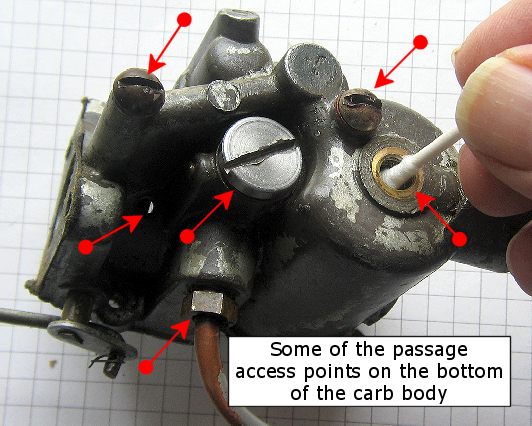
Much of the basic servicing of Johnson H and T series can be accomplished without removal of the carburetor from the outboard. However, should it be necessary to remove the carburetor from the outboard, it is relatively simple. There are five attachment points of these carburetors to the rest of the outboard (see figures below).
It is usually best to remove the gas tank first to provide access. Basic gas tank removal for the H and T series is well covered at the Big Lure/ Little Lure website. The TN-28 is further complicated by the presence of the neutral shift cable and lever and carb servicing requires tank removal. The HD-25 does not have an intake like the ones shown in the figures below. An alternative servicing procedure is described at the end of this article.
The servicing on all H and T series outboards is the same for float and primer pump washer replacement.
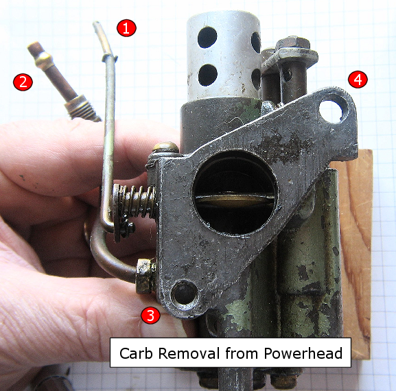
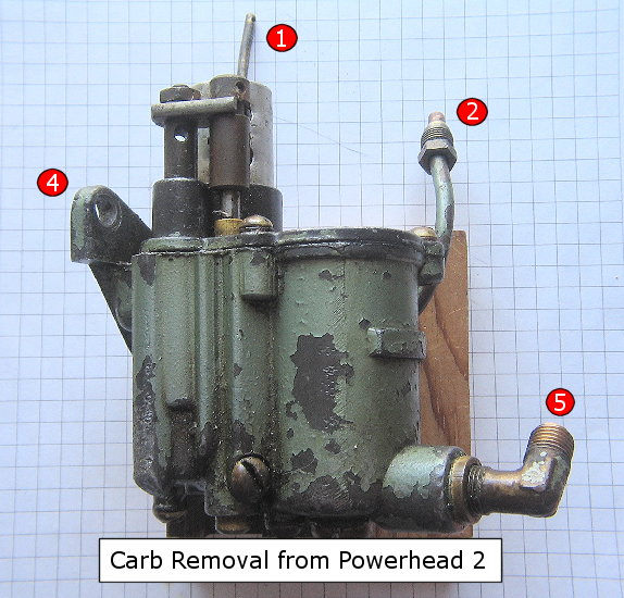
The two figures above show the five points of attachment of the carburetor to the outboard. I have found it easiest to remove the attachment points in the order 1 to 5 but this is a personal preference. Attachment Point 1 requires the removal of the wire from the butterfly actuator. The other attachment points require a screwdriver (3) and open-end wrenches.
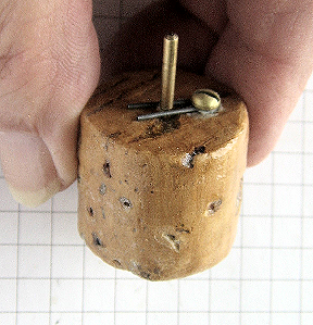
Once the carburetor has been removed, the next step is to remove the carb top plate to provide access to the float and primer pump.
This is done by removing the 3/8 nut and washer from the primer pump and sliding off the spacer bar connected to the top of the high speed jet needle assembly. Slide off the top brass fitting from the assembly to expose the top of the high speed jet needle.
The carb cap is then removed by the the three screws indicated by the blue arrows in the figure below. Only two screws hold the the smaller H series carb caps.
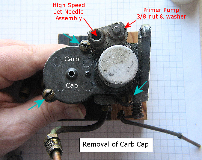
The carb cap is removed by first removing the nut and washer from the top of the primer pump and removal of the connecting bar and sliding cylinder from the top of the high speed assembly. The cab cap can then be removed by unscrewing the three screws indicated by the blue arrows.
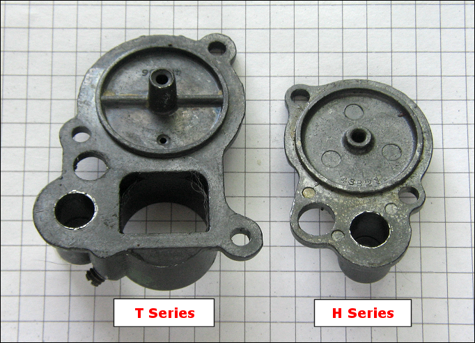
Differences between the carb caps of the smaller H series versus the larger T series. The gaskets to fit each type is also different.
Float Inspection and Removal
With the carb cap removed, a visual inspection of the top of the cork float and float pin can be made.
Any visible corrosion of the float pin and/or browning/flaking of the shellac of the float indicates float and float pin maintenance is required.
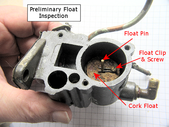
The carburetor body with the primer pump and high speed needle jet assemblies removed. Removal of the carb top allows for inspection of the contents of the float chamber. The cork float is maintained in the chamber by the float clip and a small screw. The clip fastens to the float pin by a small indentation.
The float is removed by unscrewing large float chamber screw found at the bottom of the float chamber. Next, either unscrew the float pin clip and screw from the top of the float or gently temporally widen the clip with a small screw driver to free the clip from its detent.
Once the float clip is free of its detent, push the float pin down and the pin will be driven out of the bottom of the float chamber. The float is then removed from the chamber for further inspection.
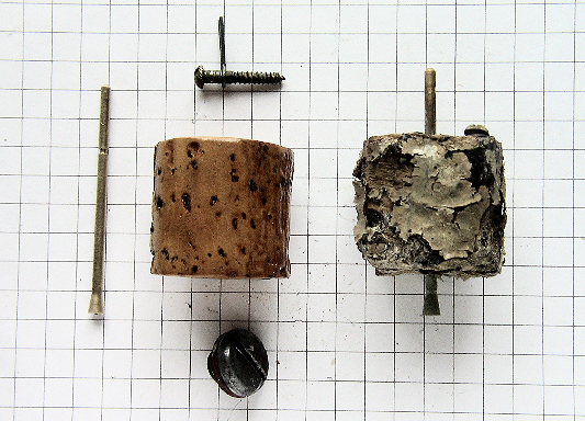
Shown on the right is a severely damaged cork float and a corroded float pin. the left shows a relatively good float with its pin clip and screw and the large access screw at the bottom of the float chamber. The float pin detent can be seen near the top of the float pin.
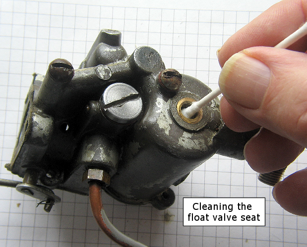
The base of the float pin acts as a valve to allow fuel into the carburetor. Any corrosion of the float pin base requires it to be cleaned of corrosion as well as the seat of the float pin (found at the bottom of the screw opening to the float chamber). If this is not done the float valve will remain "open" and flooding of the chamber will occur.

 Bad or "sinking" carb
floats or corrosion on the float pin base or corrosion in the float chamber will
stop float travel and will result in flooding of the chamber causing fuel to leak
out of the float pin hole and around the carb top gasket.
Bad or "sinking" carb
floats or corrosion on the float pin base or corrosion in the float chamber will
stop float travel and will result in flooding of the chamber causing fuel to leak
out of the float pin hole and around the carb top gasket. If the outboard has been in storage for a long time, corrosion of the float pin can occur. Lloyd Lautner (senior member of the AOMCI) suggests that simply running of the outboard can often vibrate the corrosion loose.
He further states that using grinding compound on the base of the pin and its seat (like trying to "seat" an automotive valve) is not advisable.
Many methods can be used to clean the float pin and its seat including carb cleaner, ATF fluid mixed with acetone (50:50) and alcohol. For surface corrosion I personally like a wipe down with a soft cloth soaked with Kaboom bath, tub and tile cleaner or a (50:50) solution of Pine-Sole and water. The latter is especially good at overnight cleaning of brass.
Float Maintenance and Replacement
Most of vintage outboard cork floats are still just fine after all these years. For a partially corroded cork float or routine maintenance on one, there is no need to strip off the old finish. Remove the old oil from the surface with acetone, lacquer thinner, alcohol, or carb cleaner, and then dry it out thoroughly before applying model airplane dope.
Next, light sand the surface using 300 grit wet & dry paper. Be careful to avoid cutting into the cork and reducing it's mass. Just lightly sand the shellac so the new coating will adhere a clean surface.
After the float has been cleaned and completely dried, Lloyd Lautner suggests that 2 or 3 THICK coats of model airplane dope (the "Fuel Proof" type. See note below) be brushed on and let dry for about an hour. This will seal the cork. A little thin CA Super Glue in the float pin hole and screw hole also helps. After drying, the float can be reinstalled into the float chamber.
For severely blackened, shrunken or falling apart cork floats, replacement is necessary. Lautner suggests buying a cork bottle stopper at ACE hardware. Glue the head of an old hex bolt to the top of the cork with a spot of super glue.
Chuck the bolt into a drill press or hand drill. While the
cork is spinning use a piece of 80 grit sandpaper to sand the cork down to the right
diameter. Use a hack saw blade while the cork is spinning to cut the cork to
the right length.
Demel-like and Multifunction cutting and sanding tools can
greatly aid this process.
A perfectly sized cork will fall off the drill. Drill a hole down the middle for the float pin and screw the little brass retainer screw into the cork. Put a little CA Super Glue into both holes to seal and strengthen them, then redrill the float pin hole.
Paint the float with two or three thick coats of model airplane dope (dries very fast). Use the same process as sealing/coating a reused cork float. Let dry and reinstall. Try it. It's simple.
Replacement plastic floats are also available from Mercury (part number 1395-8983) and NAPA (part number 18-7208). These will need to be modified to accommodate the Johnson float pin.
New carburetor cork float (left) being prepared for cutting, sealing and drilling from a cork bottle stopper. Finished float on right.
Orifices
A good indication of the extent of internal corrosion and plugging of the orifices of a carburetor is the examination of the check valve screen found at the bottom of the carburetor body next to the float valve screw.
Severe clogging of the screen with corrosion indicates that the passages of the carburetor will need to be cleaned.
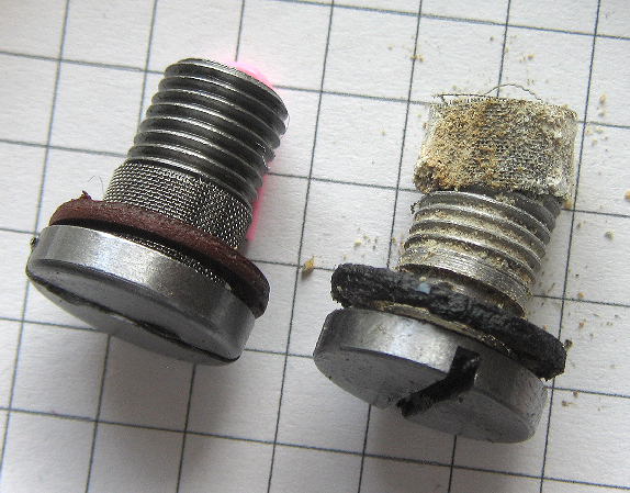
Two check valves shown, one clean and one filled with corrosion. The amount of corrosion on the check valve on the right would indicate that the passages in the carburetor body will need to be cleaned.
The fiber washer on the right shows also signs of deterioration and should be replaced. Fiber washers are found under the check valve and float chamber screw as well as other places on the outboard such as the drain screws. Small nylon washers can be used as a replacement. They are available from ACE Hardware. They fit perfectly, and are tougher than the original fiber washers.
Primer Pump Leather Seal Replacement
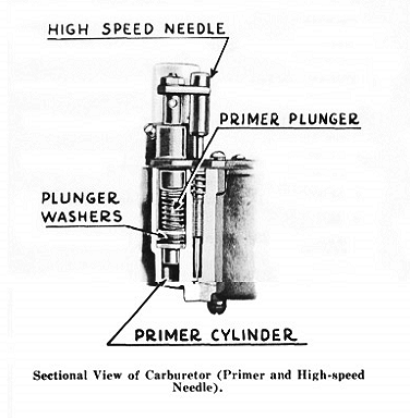
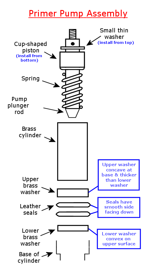
Drawing of Primer Pump and High Speed Jet Assemblies from a Johnson service manual.
The leather plunger seals ride within the primer cylinder and act to draw fuel into the cylinders to start the outboard. The action of the primer pump is much like a bicycle pump.
After removal of the High Speed Jet and Primer Pump assemblies from the carb body, the brass tube, plunger washers and leather seals will undoubtedly remain in the primer cylinder. At this point, some fabrication of extraction tools is required.
Simple extraction hooks made from coat hanger wire or metal stock can be used to remove the 1/2" brass cylinder. Catch the bottom lip of the cylinder to pull it out of the carb body. Gentle tapping on the carb body during extraction frequently helps free the cylinder.
 IN CASE OF DIFFICULT REMOVAL OF THE BRASS CYLINDER, Lloyd Lautner has also
pointed out that the Johnson Factory Service manual recommends the use of a 1/2-13
tap. Thread it a short distance into the brass cylinder with ViseGrips till a "good
grip" is obtained. If the cylinder turns with the tap, pull the tap and the cylinder
will come with it.
IN CASE OF DIFFICULT REMOVAL OF THE BRASS CYLINDER, Lloyd Lautner has also
pointed out that the Johnson Factory Service manual recommends the use of a 1/2-13
tap. Thread it a short distance into the brass cylinder with ViseGrips till a "good
grip" is obtained. If the cylinder turns with the tap, pull the tap and the cylinder
will come with it.
If the cylinder refuses to come out, pour some Liquid Wrench into the cylinder and heat the carb body with a hair dryer to slightly expand the primer cylinder. Gently tap the top of the 1/2-13 tap to loosen the cylinder. This should free the cylinder and will not damage it.
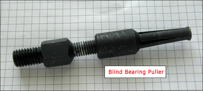
One of the easiest ways to remove a sticky brass cylinder is with a heat gun and a blind bearing puller. Although expensive, these tools will save time.
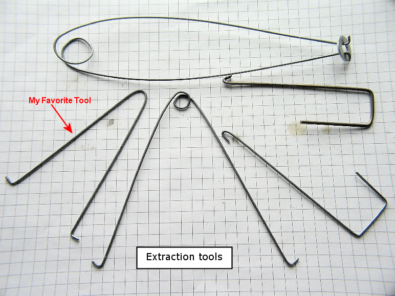
Extraction tools can be made from coat hanger wire, thin metal stock. The author found that piano or music wire (.055) worked well and was available from the local hardware store. It is important when extracting the metal washers to fashion a tool that equally pulls up on both sides of the washer otherwise it is possible to jam the washer into cylinder wall. This can damage the cylinder wall. Heating the carb body with a heat gun will also aid the extraction.
Gently VERY LIGHTLY TAP on the top brass washer with a wooden dowel to loosen it from any corrosion/fuel varnish that might be present. Lift it out with a "double hook" so that equal pressure is applied to both sides of the washer. Be careful not to damage either the washer lip or the cylinder wall on extraction. Likewise, remove the leather washers and the bottom brass washer from the cylinder.
IN
CASE OF DIFFICULT EXTRACTION OF THE BRASS WASHERS, heat can be externally applied
to the carb body with a hair dryer or hot water. This will slightly expand the plunger cylinder.
A good penetrating oil will sometimes help. Some AOMCI members have suggested using a small-sized blind hole
bearing puller to extract the washers. This
effort is also aided by applying heat to the carb body during
extraction.
After all parts of the pump are extracted, they should be
cleaned and inspected for damage. Replace any worn or damaged parts.
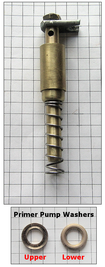
Cleaned
metal parts for Primer Pump. Be sure brass washers and leather seals are installed
in the correct orientation according to the information in the above figure. Leather
seals should be installed with the smooth side down.
Installation of the Primer Pump parts is the reverse of their extraction. The author would recommend chilling the brass washers overnight in the freezer so as to reduce their diameter. This allows for easy installation. Be sure to install the brass washers and leather seals in the right order and orientation. A small amount of penetrating oil or grease on the leather seals and a wooden dowel will help place the seals.
After reassembly of the Primer Pump, the action may be tight and might not spring back easily. This is necessary to obtain a good pump seal. This will smooth out with time as the washers and seals "take a seat" against the walls of the cylinder with continued use.
Author's Note: Much of the information contained in this article is a result of communication with AOMCI Senior Member, Lloyd Lautner. His assistance greatly helped and is much appreciated. This page was prepared by a "newbie" for "other newbies" who need help working on their carburetor.
FOR SALE JOHNSON LEATHER
PRIMER PUMP SEALS for TD, TN, etc.
If your old Johnson drips fuel from the carburetor when you push the primer, you
need these seals and instructions. If you have tried rubber O-rings or other materials,
you already know they won't work. Gaskets and cork floats are easy to make, but
these leather seals are very difficult to reproduce
so that they work properly. Don't worry. These are new seals made from pump leather,
as original, and fit all old 5 hp, 4.2 hp, and 2.5 hp Johnsons including Models
TD,TN,AT,LT,DT,HD,HA,HS, etc. Includes detailed diagrams and instructions for proper
installation that are not found in the Factory Service Manuals. The instructions
alone are indispensable. Not necessary to remove carburetor.
Send $8.00 per set (cash only, no checks) and SASE (self addressed stamped envelope) to: Lloyd Lautner, 9289 North Long Lake Road, Traverse City, Michigan 49685
Stop leaking and keep yourself and the "tree huggers" happy!
Lloyd Lautner AOMCI
Final Assembly Notes and Pitfalls:
When reassembling, here are some things to watch out for:
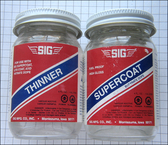
Float Coating: The fuel-proof float coating is made by SIG Manufacturing. It can be found at hobby and model airplane shops. SIG also has an excellent list of dealers by state at their website and makes a number of fuel-proof paint products.
Check Valve: must be clean at screen and internally, Blow in top of hole by mouth to assure the valve is working. There should be no air flow. If you suck up on valve, there should be air flow. Be sure sure to wash and air compress value before running "breath test" or you will have a bad taste in your mouth. Sometimes malfunctioning valves can be cleaned overnight in acetone or carb cleaner (remove washer) or Pine-Sole.After soaking some vibration like tapping on a hard surface is sometimes necessary to free the tiny ball of varnish or dirt in the valve. Blow out with compressed air, wash and retest. If failure occurs again, valve should be replaced.
Carb Cap Alignment: On reassembly, be sure that the shaft for the float pin in the carb cap aligns with the float pin. To confirm proper alignment, be sure that top of float pin can be seen through shaft hole in the carb top at final assembly.
High Speed Jet Assembly: Because of the fit, always add the High Speed Jet LAST to the final assembly of the carburetor.
Carb Cap Gasket Leakage after Re-install: Sometimes the carburetor cap gasket will leak a little on re-install. Run the outboard and allow the gasket to swell with gas and oil. It might also be that the float is stuck after the motor has not been run for a long time or the float was recently replaced. This usually will stop after a few minutes of running the outboard. If gasket continues to leak, the carb head screws might need re-tightening or the gasket might need replacement.
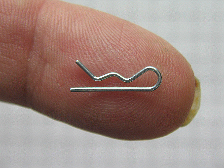
Using Linch or Wire Lock Pins: Several points of attachment on OMC outboards use fine twisted wire as an the top of the carburetor linkage arm (No. 1, above). These connections are often very difficult to to re-establish. I suggest using small wire lock pins that can be found at hardware stores instead of the original wire. Below is a picture of such a pin.
Using Pipe Cleaners on High Speed Jets: A simple "pipe cleaner" is a great tool for cleaning any fine debris or fine coating of varnish from inside the high speed jet.
If fuel still not reaching the carb: You might investigate cleaning out the gas tank fuel valve and fuel line This is covered in the fuel tank and fuel valve cleanout article at this website.
Special Servicing of the H series Carburetor: Some of the AOMCI members prefer to not remove the H series carburetor from the motor. This is because of the large air intake on the carb body. Since the intake gasket lies near to the exhaust, removing the carb body can frequently cause damage the gasket.
It is just as easy to remove the gas tank, remove and service the magneto, and remove the fuel tank bracket. This allows easy servicing of the carb plus the fuel line and fuel valve.
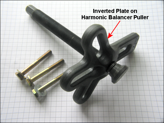
Tip: to remove the flywheel, it is necessary to use an Harmonic Balancer Puller. In order to get a satisfactory grip, It might be necessary to invert the pulling plate on the balancer as is shown in the figure below.
Tip: on the HD-25, to remove the magneto, it is first necessary to loosen the fuel tank bracket. This allows easy access to the magneto shaft screw which lies under the magneto.
To service the carburetor follow the procedure found above.