Testing
an Outboard Coil and Points with a Multimeter
using an ignition coil from the Johnson H or T Series
By Dave Poche
Modern outboard coils consist of two windings around an iron core. Complete testing of a coil often involves resistance testing of its windings but also a test of of the insulation of the coil wires. The equipment involved is often out of reach of the typical home outboarder.
Testing of any outboard coil to see if it's good is relatively simple if you following the procedures below. This simple test of the resistance of each winding will determine if the coil is potentially "good".
You will require a multimeter (either a digital or an analog like the one used in this article) with a resistance scale (x100 or x1000 or x1K) to test your coil.
- Select resistance range setting (I use x100) and connect the ends of the probes into the meter and touch the ends of the probes together. The meter should move to the right to near "0".
- Use the Ohms Adjust knob to place the meter needle exactly on the zero of the scale. This reading implies zero resistance and is the reading for "continuity" for a circuit or cable.
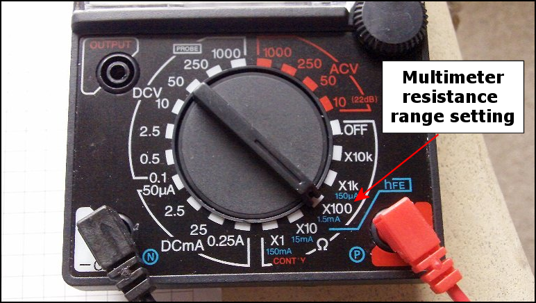
Selection dial
of multimeter set to x100 range setting. Add 2 zeros to the multimeter reading of
the scale.
If the x1K or x1000 scale is selected, then
add 3 zeros to the reading on the scale.
- Next, use the image below to find the appropriate wire connections for the Secondary Winding.
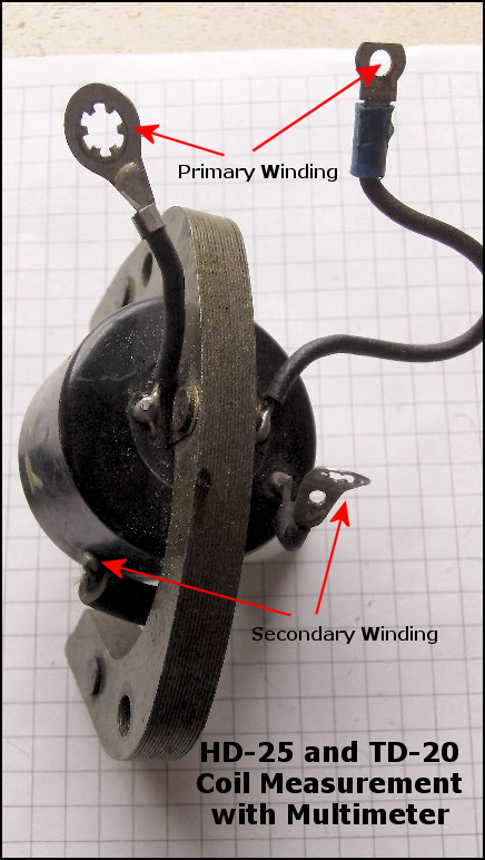
Selection points on coil for Primary and Secondary Windings. Multimeter probes are connected across the indicated points to measure the resistance in ohms of the winding.
- Next, connect the multimeter probes across the two connection points of the Secondary Winding. This circuit contains the spark plug wire. Either red or black colored probes can be connected to either point.
- The multimeter reading is shown below (see topmost scale). Since the range setting is set to x100, add 2 zeros to the meter reading to get the resistance.
- The meter reads a resistance of 3600 ohms. Any resistance of 3000 to 8000 ohms is a "good coil reading" for the Secondary Winding.
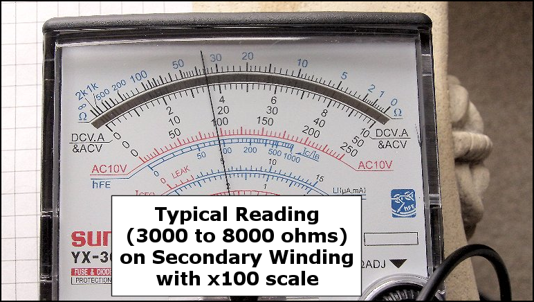
The reading of the topmost scale of the multimeter (ohms scale) shows the measured resistance across the coil's Secondary Winding selection points. Any resistance reading between 3000 to 8000 ohms is a "good" for the coil's windings. Since the range setting is set to x100, add 2 zeros to the meter reading (36 on scale plus 2 zeros = 3600 ohms). If the x1000 range setting was used, then the reading would be to the right, slightly beyond the number "3" on the scale. In this case, 3 zeros would be added to the scale reading. It's best to choose a resistence scale with readings near the middle of the meter range.
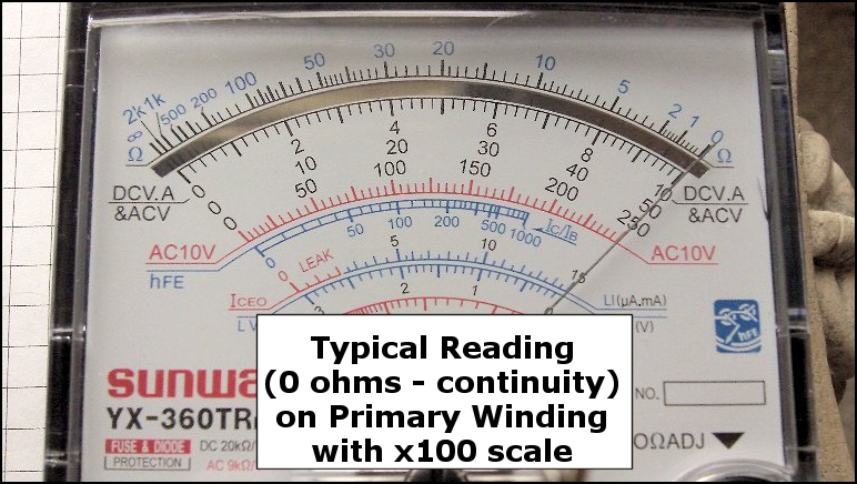
- Next, measure the resistance across the two connection points of the Primary Winding of the coil.
- The meter should swing all the way to the right to zero resistance, if the coil's Primary Winding is "good". This shows "continuity" or a connected circuit across the connection points.
- The continuity of any wire (like spark plug wires) can be tested in this manner.
If both the Primary Winding and the Secondary Winding of the coil test as "good" then the coil is good to go but keep in mind it might not tell the full story.
if you have a 2 cylinder outboard motor with spark at one cylinder, you might try a further test by swapping the two coils between the cylinders and see if the spark moves to the other cylinder. This also works for checking condensers, spark plugs, and spark plug wires.
Testing the Prufrex Coil
Prufrex (German-made) coils were used on later OMC outboards. These coils and their NAPA replacements are different from the above coils in that they have only 3 testable leads to make measurements from. One of the leads (non-condenser side wire) is used for resistance measurements on both the primary and secondary coil windings.
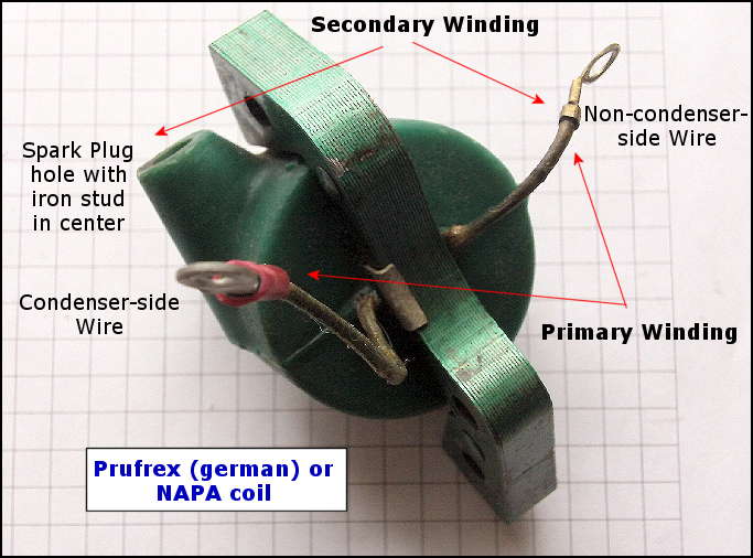
The Prufrex outboard coil showing the contact points for resistance readings of the primary and secondary coil windings. When testing the secondary winding, it be necessary to use the irom stud inside the spark plug tunnel or simply measure at the end of the spark plug wire.
Primary resistance is measured across the two wires extending from the coil (Condenser-side and Non-condenser side wires). A potentially "good" coil will read 0 ohms or continuity across these leads. This is after the Ohms adjust and scale setting of the multimeter has been made as described above.
A potentially "good" reading for the secondary winding is in the range of 3000 to 8000 ohms. The connection for this reading will be between the iron stud in the spark plug wire tunnel or at the end of the spark plug wire and the non-condenser side wire.
The readings are exactly the same as the
older coils.
Testing the Points
The magneto points are frequently dirty and oxidized and need to be cleaned/filed/honed until they are shiny bright metal and they need to be removed from the magneto to do so.
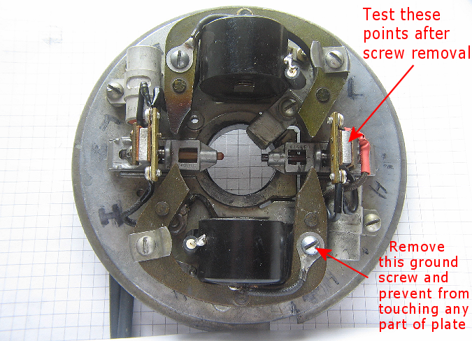
The points and magneto shut-off switch can be checked for cleanliness after cleaning by isolating the coil primary from ground, do this by removing the screw holding the ground side of the primary coil (bare wire with a ring terminal), move the wire clear of any ground contact.
Add a clip lead to one of your multimeter leads and re-zero the resistance between the two leads coming from the multimeter. Connect the clip lead to one side of the points circuit as shown below.
Check the resistance as shown below across the points, clean points should show zero ohms when closed (see picture below).
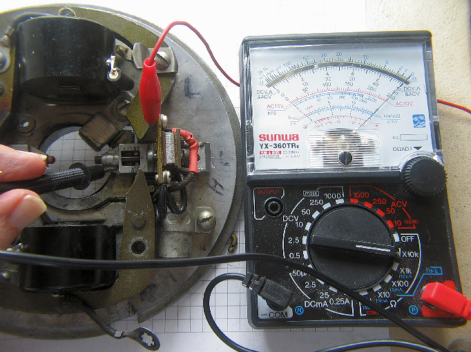
Measuring the closed points position. If the points are clean then the multimeter should read zero ohms as figure above shows.
To check the open position of the points, touch the lead at the same location but gently push the bakelite plunger in with the middle finger. Do not ground your fingers to any part of the magneto plate. When points pressed open, you should read "open" or 10,000 ohms in this case as shown in the figure below.
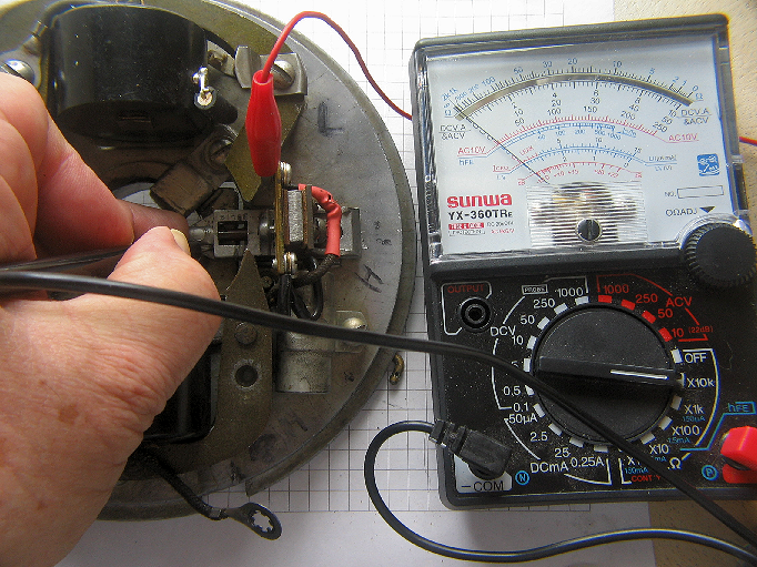
Testing the open position for the points. Gently press in the bakelite plunger with the middle finger. Be sure not to ground your fingers against any part of the magneto plate to obtain a good reading. Reading should be about 10,000 ohms.
Check both sets of points. If you see any significant multimeter readings, this is an indication that you have an unwanted ground that maybe be either dirty points or a bad connection at the magneto shut-off connection.