Johnson TN-28 Impeller Substitution
By David Poche
Impeller replacement of the Johnson T series can be accomplished by modification of more recent Johnson impellers to fit the shaft of the T series. The modification is relativly simple and saves money in the process.
The impeller chosen for the modification to the 5.0 hp TN-28 (OMC part 375688) is the Sierra impeller 18-3001. This impeller normally fits on the Johnson 5.5 hp (1954-1964) or the 3.0 hp (1952-1972). The Sierra 18-3001 has the following dimensions: outer diameter= 2.75 in.; shaft bore = 0.43 in.; thickness = 0.50 in.; and key = 0.145 inches. With the exception of the shaft bore, these are identical to the impeller of the TN-28.
The 18-3001 is available from many stores that offer Sierra products including NAPA and O'Reilly auto parts stores.
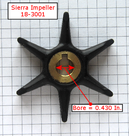
Sierra impeller 18-3001 can be used as a substitute for the TN-28 impeller. This requires that the bore be enlarged to 0.440 to fit the shaft of the TN-28.
Impeller Replacement
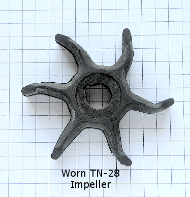
Worn impeller removed from TN-28 shows fin folding and excessive wear on folded fins.
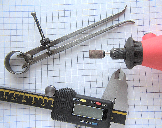
Bore modification can best be accomplished with mechanics tools, electronic calipers and Dremel-type tools. The total time to resize the impeller bore was less than 10 minutes.
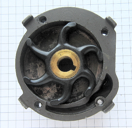
Correct orientation of impeller blades in pump housing according to service manual
Impeller Reuse
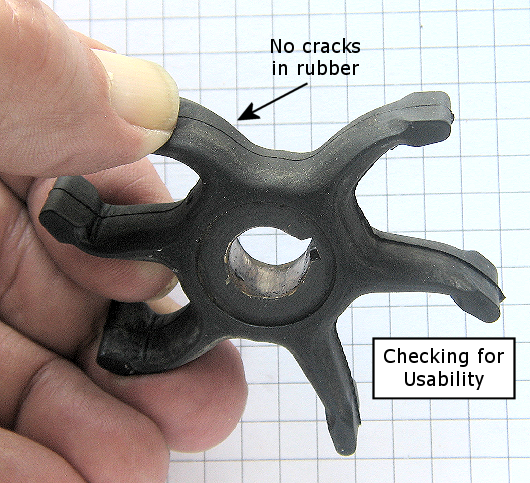
Checking old impellers for reuseability
Author's Note: Thanks to Lloyd Lautner, Senior Member of the AMOCI, for lending his expertise to the author on this project.
Lower Unit Notes:
When removing lower unit, here are some things to watch out for:
Drain Lube Oil First: Unless you want lube oil all over your assembly area, it is best to drain the lube oil from the lower unit before disassembly. Be sure to check the color of the oil as white milky oil may indicate water invasion.
Difficulty Removing Lower Bushing and Spring From Lower Shaft: Sometimes disassembly of lower shaft will be difficult due to small burrs on the shaft near the bottom. This results from shifting into neutral at high speed. The shaft will have to be cleaned of these burrs before access to water pump and removal of the impeller can be accomplished.
Difficulty Installing New Clutch Cable: If part of your maintenance involves a new clutch cable, It can be difficult to install the new cable through the turns of cable tube to the top of the outboard. First, grease the wire with waterproof axle grease and then feed it up the tube. If it jams on the way up, twist the cable in the direction of the cable twist. This will sometime free the jam.
Further Discussion by Members of the AMOCI Regarding H and T Series Impeller Replacement: Be sure there is no gaps around the the impeller rotor and propeller shaft and around the rotor/pump housing as shown in the diagram below. Sometimes this is due to a worn eccentric shaft and/or impeller.
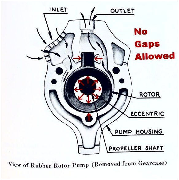
If you put in a new impeller/rotor, be sure it is not too thick for the housing. Some of the new ones are too thick and will bind inside the housing and not pump well or at all when the housing is screwed on tight. Put the rotor inside the housing and lay a metal straight edge over it to be sure it is not above the edges of the housing. Sand it down on a flat surface if necessary.